THIS WEBSITE, THE BRIGHTON BRANCH OF A.S.L.E.&F.
HAS NOW BEEN MOVED TO A NEW SITE CALLED
IGNITING THE FLAMING OF UNITY
http://ignitingtheflameofunity.yolasite.com/1933-brighton-line-resignalling.php
PLEASE CLICK ON THE IMAGE BELOW TO TRANSFER TO THIS NEW SITE
CLICK ON THE ABOVE IMAGE TO TAKE YOU
TO THE NEW UPDATED COMBINED AND WEBSITE
IGNITING THE FLAME OF UNITY WEBSITE
THIS WEBSITE COMBINES THE FOLLOWING WEBSITES
THE BRIGHTON A.S.L.E.&F., THE BRIGHTON MOTIVE POWER DEPOTS
& THE SUSSEX MOTIVE POWER WEBSITES
WHICH EXPLAINS THE EVOLUTION OF THE FOOTPLATE GRADES AND THE HISTORY OF THEIR TRADE UNIONS AND THE STRUGGLES TO IMPROVE THEIR WORKING LIVES
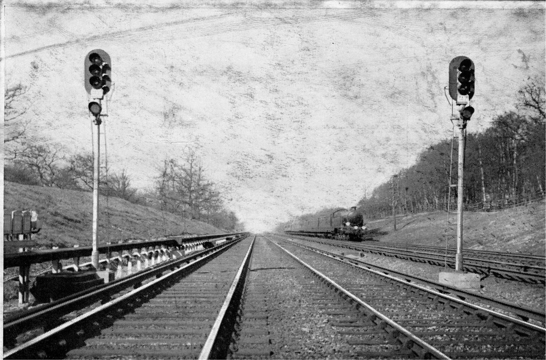
Looking North From Balcombe Tunnel Junction
Brighton Line Signalling
On Whit-Monday, 1933, 107 trains left Brighton in five hours,
carrying 75,000 passengers
The combination of good weather and improved travelling facilities resulted in a great increase of passenger traffic on the
Southern Railway during the Whitsun recess. During the whole holiday period no less than 129,165 passengers were
conveyed to Brighton, mainly by electric trains. This represents an increase of 75 per cent, over last year. On Whit-Sunday the
number of people carried to Brighton showed an increase of 174 per cent, over last Whit-Sunday, while on Whit-Monday the
increase was 68 per cent.
Reprinted from “ Modern Transport," June 10th, 1933
In the course of the homeward rush from the seaside on Monday evening last, there were several achievements on the part of
the Southern Railway calling for attention. At Brighton a special control tower was installed and brought into use about 4
p.m., its object being to direct passengers to the various platforms and trains. Between 5 p.m. and 10 p.m. no fewer than 107
trains left Brighton Central Station, carrying 75,000 passengers. On the average, therefore, a train departed every three
minutes—or slightly less—throughout the five hour period, and each train carried on an average just over 700 passengers—
15,000 an hour. The great bulk of this traffic was for London or beyond, and had to be carried over the main line, which has
only the one up track as far as Balcombe Tunnel box—19 miles—and in addition to the trains from Brighton there were those
from Worthing and Hove also passing over almost the whole of this distance. More noteworthy still is the fact that from
Keymer Junction to Balcombe Tunnel there were also the Hastings, Bexhill, Eastbourne and Seaford trains to be
accommodated by the single up road in addition to those from Brighton and Worthing. Actually, between Keymer Junction
and Haywards Heath the up trains moving over this road were : between 7 and 8 p.m., 13 trains ; between 8 and 9 p.m., 16 ;
between 9 and 10 p.m., 18 ; and between 10 and 11 p.m., 14 trains, the greatest density being one every 3'3 minutes
throughout the hour. Only by the employment of automatic colour-light signal- ling, and of very heavy electric trains for the
most part, could this traffic be moved within so short a period.
Reprinted from “Railway Gazette," June 9th, 1933
THE WESTING HOUSE BRAKE & SAXBY SIGNAL Co., Ltd.
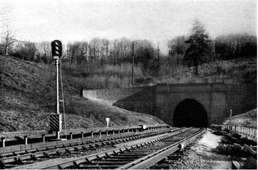
Balcombe Tunnel Northern end
It will be recalled that between the years 1925-1929 the Southern Railway carried out an extensive programme of signalling
conversion in the inner London zone and installed during that period a complete power signal system, entirely of
Westinghouse manufacture, at Charing Cross, Cannon Street, Borough Market Junction, London Bridge and New Cross, and
on the tracks linking up these stations. This power system covers about 471/2 track miles, carrying an extremely intense
suburban traffic in addition to heavy coastal services of both passenger and goods trains.
With the extension of the Electric Service to Brighton and the resultant greatly increased train service, complete
reorganisation of the signalling arrangements became a necessity. The valuable experience gained on the London power
signalling showed that a similar system, modified to comply with the characteristics of the Brighton Line, would give the
required facilities, and in making the decision to introduce power signalling between Coulsdon and Brighton the Railway
Company have added a further 119 track miles of line which are provided throughout with colour light signals and continuous
track circuits. As the electrification of the London to Brighton line constitutes the longest section of electrified railway in
Great Britain, so the signalling comprises the greatest length of continuous track circuiting and complete power signalling on
a British main line. Westinghouse apparatus was again selected as possessing that essential reliability necessary to withstand
the severe operating conditions on the 36 miles of route, and advantage was taken of several new developments and
improvements to apparatus, although, in general, the design of apparatus called for follows closely upon that which has
proved equal to all the demands made on it during the previous four years.
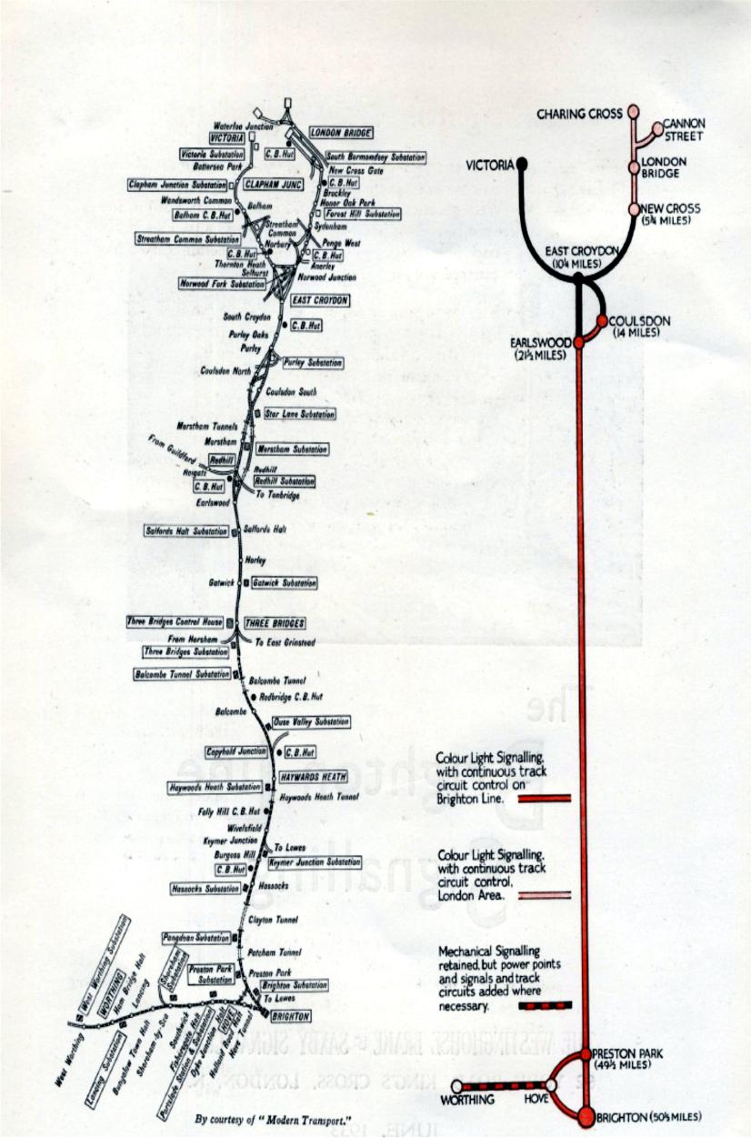
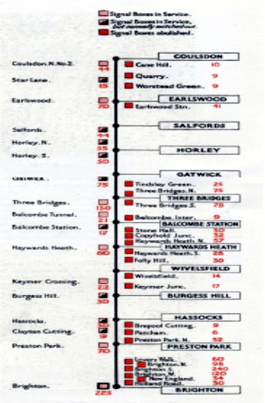
The map and key plan opposite show the line between London and Brighton, and it will be seen that East Croydon is the
Junction for all trains to and from the various London termini. The power signalling commences at Coulsdon North about 14
miles south from Victoria and continues through Earlswood Junction to Three Bridges. Three Bridges is the junction for the
Horsham and Portsmouth line to the south-west, and for the East Grinstead and Tunbridge Wells line to the east ; in addition,
it is of importance owing to the presence of extensive goods sidings, locomotive running sheds, and the main control station
for the remote control of all traction sub-stations on the Brighton line. There are four running roads between Earlswood and
Balcombe Tunnel, which is about 2f miles south of Three Bridges, the signal cabin situated at the north end of the tunnel
having the control of the junction from the four to two roads. The line diverges into four roads again between Copyhold
Junction and Hayward's Heath Station, then reverts to double-road track, continuing thus to Preston Park. A branch line
junction at Copyhold is controlled from Hayward's Heath Cabin, about miles distant, crossovers being provided for the
routing of trains for running into the required platforms at Hayward's Heath. Plans of the track and signal layout at Three
Bridges, Copyhold Junction and Hayward's Heath, will be found at the end of this publication.
A short distance south of Hayward's Heath is Keymer Junction, where the line to Lewes and Eastbourne diverges. Preston
Park is on the outskirts of Brighton, the cabin having control of all traffic to and from London, and it is here that trains
running direct between London and Worthing are diverted. Brighton Station lies about 1/2 mile south of Preston Park Station
and besides being the terminal station of 10 platforms for London to Brighton traffic, it is also a terminal and junction for the
Hastings line to the East and the Worthing and Portsmouth line to the West (the line joining that from Preston Park at Hove).
There are extensive goods marshalling sidings at Brighton as well as locomotive running sheds, locomotive and carriage
repair shops, large carriage sheds and washing plant for electric stock.
The general signalling scheme employs three-aspect colour light signals throughout for running signals and two-aspect
colour light signals for shunt movements. Exceptions to the general rule are to be found in cases where it has not been
possible to obtain full braking distance, and here four-aspects have been used to maintain the necessary flow of traffic. With a
single exception all other types of signals, such as call-on and warning signals have been eliminated, thus adding greatly to
the uniformity and simplicity of the system without interfering in any way with expeditious handling of traffic.
The system of control adopted between Coulsdon and Preston Park, a distance of approximately 31 miles, is electro-
mechanical with continuous track circuiting of all running roads, and track circuit fouling protection of junctions and sidings.
At Brighton the system is all-electric, controlled from a new cabin containing a 225-lever power frame. In the electro-
mechanical section certain cabins were selected for retention in service and all others have been abolished. The selected
cabins are those from which the routing of trains is always being carried out, or where there is at times some shunting of
goods trains, or where special regulation of traffic may occasionally be necessary. Reference to the diagram on page 21 will
make clear the number of cabins totally abolished, those which are normally switched out, and those, such as Earlswood,
Three Bridges, Hayward's Heath, Keymer Crossing and Preston Park, which are always in service.
No distinction has been made between the two classes of cabins in the matter of equipment, except, that at Hayward's Heath
and Three Bridges it was found necessary to install new Style A.2 locking frames of 54 levers and 125 levers respectively. In
all cases illuminated track diagrams of the spot-light type are provided, together with illuminated indicators for colour light
signals and power points. In a number of cases facing points and siding connections are situated too far from the cabin to be
manually operated, and therefore high speed style M.3 point machines and colour light shunt signals have been installed,
controlled from slightly shortened levers in the mechanical frames. Mechanically-worked dwarf signals are retained where
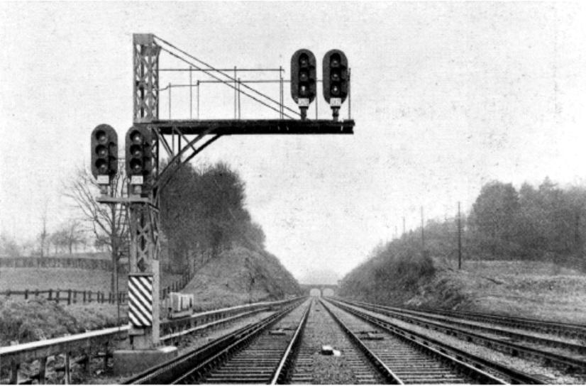
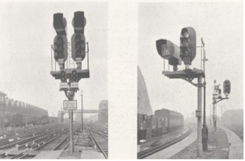
distances are not too great, as also are semaphore arms on lines joining the main route. At the entrances to the colour light
signalling area the semaphore distant signal arms are replaced by two-aspect colour light signals, which normally show no
light, but are brought, into operation by the clearing of the stop arm above them. Such a combination is illustrated on page 6.
All points in the track-circuited area, or which lead on to the running roads, are electrically detected, and all point levers are
fitted with Style D lever locks and circuit controllers to track-lock the lever in the Normal and Reverse positions ; facing point
bolt levers are locked in the Reverse position only. Many signal levers have electric lever locks of the Style E pattern, to lock
the lever in the Normal Indication position for backlocking.
It has been possible, in the majority of cases, to house most of the apparatus in the lower compartment of the signal cabin.
The apparatus to be accommodated consists of single element Style H.2 A.C. line relays for signal control, double element
Style G.2 A.C. track relays, and Style G.2 three-position vane point detector relays, together with the necessary transformers,
rectifiers for the point machines, and, of course, the requisite fuses, power supply switches, etc. All track feed sets are located
outside the
cabin in separate feed cases, and in a number of instances, the track relays are also housed outside the
cabin.
The general signalling scheme employs three-aspect colour
light signals throughout for running signals and two-aspect
colour light signals for shunt movements. Exceptions to the
general rule are to be found in cases where it has not been
possible to obtain full braking distance, and here four-aspects
have been used to maintain the necessary flow of traffic. With
a single exception all other types of signals, such as call-on
and warning signals have been eliminated, thus adding greatly
to the uniformity and simplicity of the system without
interferring in any way with expeditious handling of traffic.
The system of control adopted between Coulsdon and Preston
Park, a distance of approximately 31 miles, is electro-
mechanical with continuous track circuiting of all running
roads, and track circuit fouling protection of junctions and
sidings. At Brighton the system is all-electric, controlled from
a new cabin containing a 225-lever power frame. In the
electro-mechanical section certain cabins were selected for
retention in service and all others have been abolished. The
selected cabins are those from which the routing of trains is
always being carried out, or where there is at times some
shunting of goods trains, or where special regulation of traffic
may occasionally be necessary. Reference to the diagram on
page 21 will make clear the number of cabins totally
abolished, those which are normally switched out, and those,
such as Earlswood, Three Bridges, Hayward's Heath, Keymer
Crossing and Preston Park, which are always in service.
No distinction has been made between the two classes of
cabins in the matter of equipment, except, that at Hayward’s
Heath and Three Bridges it was found necessary to install new
Style A.2 locking frames of 54 levers and 125 levers
respectively. In all cases illuminated track diagrams of the
spot-light type are provided, together with illuminated
indicators for colour light signals and power points. In a
number of cases facing points and siding connections are
situated too far from the cabin to be manually operated, and
therefore high speed style M.3 point machines and colour light
shunt signals have been installed, controlled from slightly
shortened levers in the mechanical frames. Mechanically-
worked dwarf signals are retained where distances are not too
great, as also are semaphore arms on lines joining the main
route. At the entrances to the colour light signalling area the
semaphore distant signal arms are replaced by two-aspect
colour light signals, which normally show no light, but are
brought, into operation by the clearing of the stop arm above
them. Such a combination is illustrated on page 6.
All points in the track-circuited area, or which lead on to the
running roads, are electrically detected, and all point levers
are fitted with Style D lever locks and circuit controllers to
track-lock the lever in the Normal and Reverse positions ;
facing point bolt levers are locked in the Reverse position only.
Many signal levers have electric lever locks of the Style E
pattern, to lock the lever in the Normal Indication position for
backlocking.
It has been possible, in the majority of cases, to house most of
the apparatus in the lower compartment of the signal cabin.
The apparatus to be accommodated consists of single element
Style H.2 A.C. line relays for signal control, double element
Style G.2 A.C. track relays, and Style G.2 three-position vane
point detector relays, together with the necessary
transformers, rectifiers for the point machines, and, of course,
the requisite fuses, power supply switches, etc. All track feed
sets are located outside the cabin in separate feed cases, and
in a number of instances, the track relays are also housed
outside the cabin.
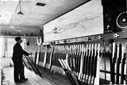
Haywards Heath Signal Cabin
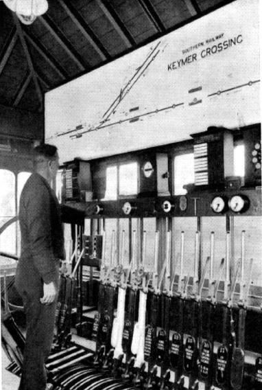
Keymer Junction Signal Cabin
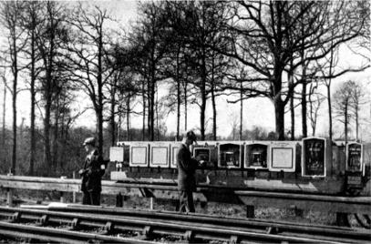
An interesting feature of the point machine control at the
electro-mechanical cabins Is the provision of special
arrangements for hand-operating the machines. The crank-
handles kept at any cabin are constructed in such a way that
they are not interchangeable among the machines, but only fit
their own particular point machine or group of point
machines. The handles are kept normally in separate circuit
controllers (see illustration opposite) whose contacts break the
point control and detection circuits for the machine concerned,
when the crank-handle is removed. Padlocks are placed on
each controller to prevent unauthorised removal, the key being
retained in the cabin behind a glass-fronted box for use in
emergency, and a duplicate is in the possession of the lineman.
The object of these precautions is to eliminate any possibility
of confusion leading to illegitimate hand-operation of a
machine in an emergency or during maintenance duties.
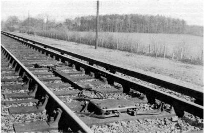
The apparatus outside the cabins, is uniform in design
throughout the line. Track circuits at crossings and junctions
are single-rail, while those for the remainder of the line are
double rail. Owing to the third-rail system of traction,
impedance bonds are employed on all double-rail track
circuits, and in some cases additional impedance bonds are
placed intermediately for cross-bonding purposes on the
traction system. The average length of a double-rail track
circuit is about 1,500 yards.
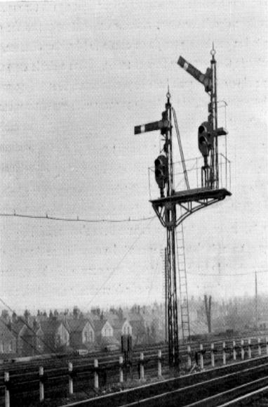
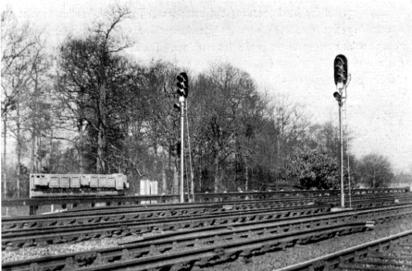
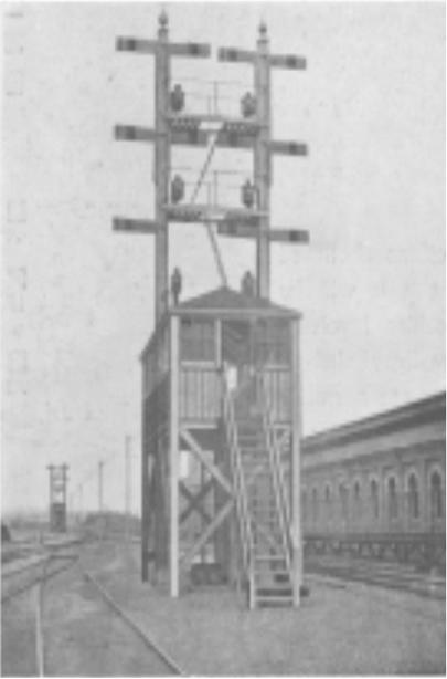
Upper-quadrant Semaphore signals, with 2 aspect Colour-
light Distant Signals - Earlswood Junction
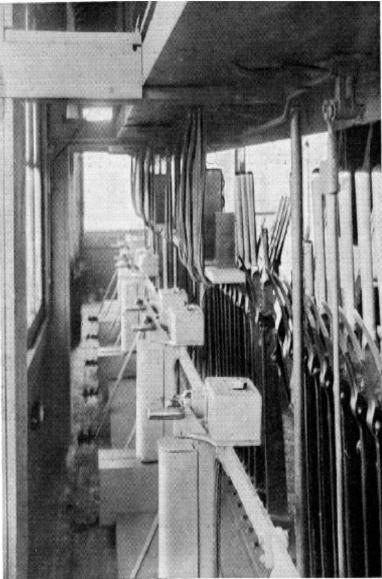
Points Machine Crank Handles and Interlocked Circuit
Controllers Earlswood Junction Cabin
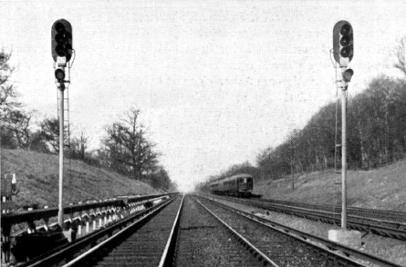
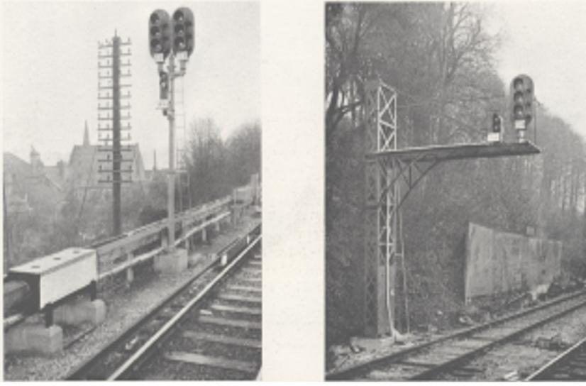
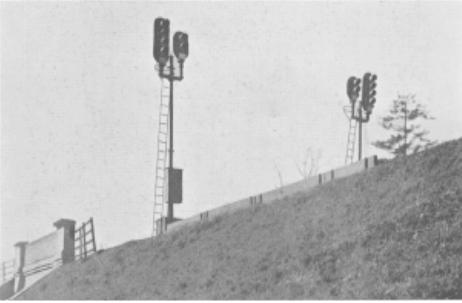
The running signals are of the standard Westinghouse long-range pattern, having double filament 12-volt, 25-watt, 3-pin
lamps ; in addition to the auxiliary light deflecting unit in each aspect, separate sidelights have been fitted on all signals on
the installation and have proved of great benefit to motormen of electric trains, which can draw up very close to a signal. All
automatic signals between cabins are distinguished by an " A " light mounted just below the main signal, the " A " being
illuminated only when the red aspect is showing above it. Typical automatic signal locations are illustrated on this page and
page 9, those on this page showing the apparatus cases which contain the signal control relays, track feed sets, and track
relays. Signals which are sometimes controlled from a cabin and at other times work as " automatics " also carry " A " lights,
such " A " lights being cut out when the signal is " controlled." Exceptions to this arrangement are the fully automatic signals
located at entrances to tunnels ; such signals are not fitted with " A " lights, as the " one minute rule " does not apply at
tunnels. The auto-signal at the entrance to Balcombe Tunnel, illustrated on the frontispiece, is an instance of this. If a train is
stopped by a red aspect at one of these signals (also at any controlled signal) the driver or motorman must communicate with
the nearest signal cabin by a telephone contained in a black and white striped box fixed to the signal post or nearby
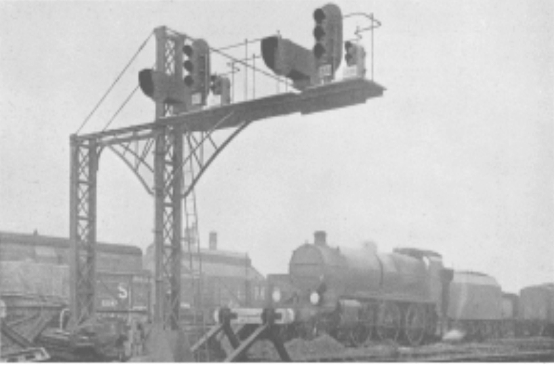
Most of the signals are mounted on pipe posts, although several bracket arrangements are to be found. The illustration of
Copyhold up home signals below is an instance of a very compact structure built in our shops. Shunt signals, one of which is
illustrated at the bottom of this page, are of the globe type similar to those used at London Bridge, and display the usual Red
and Green aspects with the exception of a few siding signals which have Yellow and Green aspects
Copyhold Junction
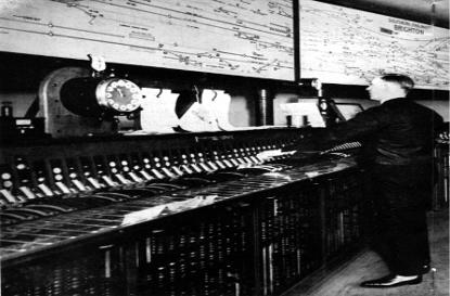
Three Bridges Cabin during installation of the new Locking
Frame
Three Bridges Cabin, as it now appears
Before going on to describe the apparatus at Brighton, special mention must be made of a notable signal engineering feat
carried out at Three Bridges. Originally there were three cabins, but under the new arrangement one cabin was to handle the
whole of the work, the Central Cabin having been selected for the purpose. This cabin contained an old Saxby rocker frame of
94 levers which, it was found, could not be converted satisfactorily ; it was decided therefore to install a new 125-lever
Westinghouse Style A.2 frame, which was actually erected in the cabin opposite the old frame as shown above.
On the night of bringing into service of the new signalling, the new frame was connected up and the old one disconnected and
eventually taken out, without any interference to traffic. The completed interior of the cabin as it now appears is illustrated
below.
Referring now to the signalling at Brighton itself, it has already been mentioned that a new 225-Iever power frame has been
provided. The new cabin takes the place of six old cabins and the 225 power levers do the work of 562 mechanical levers.
An exterior view of the cabin is given on page 14, the windows
shown being those of the main operating room, directly behind
which is the relay room and linemen's mess room. Access to
the cabin is by a former signal bridge now devoid of signal
dolls and, in addition to being a walkway, serves to carry
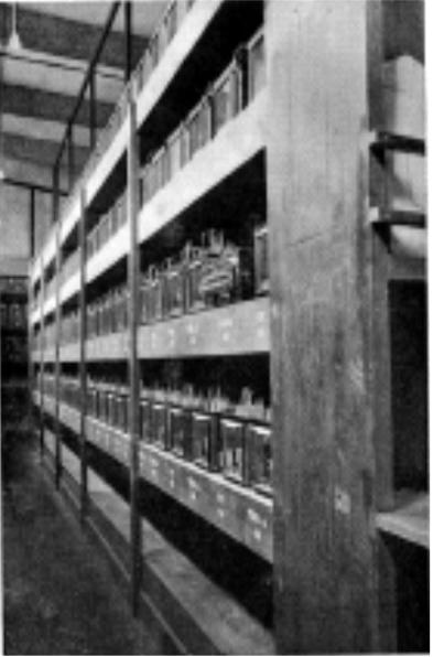
many of the signal cables. It may here be mentioned that, when
the previous remodelling of Brighton Station in 1881, was
carried out, a special subway was constructed under the
running lines to accommodate point rods and signal wires.
This subway, shown above, which has been extended, proved
of considerable value, as it has been employed as an
additional means of conducting cables from the down side
across to the Worthing Branch. A general view of the interior
of the cabin is given on pages 12 and 13, and clearly shows
the power frame and illuminated diagrams.
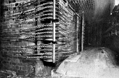
Subway under the lines at Brighton Station showing old
mechanical connections now used for signal cables.
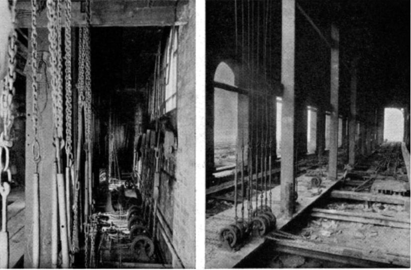
Mechanical Point and Signal Connections under old cabins at Brighton, now removed
The power frame is a Westinghouse Style all-electric with no mechanical lever interlocking. Full advantage has been taken of
the flexibility of the all-electric frame by dividing the levers into three sections, the two end sections being placed at an angle
to the middle section. This arrangement saves a considerable amount of cabin space and at the same time increases very
noticeably, the ease of co- operation between signalmen, and observation of the diagrams. Electric lever interlocking is
provided on all levers and is laid out to give the same effect as mechanical lever interlocking.
All signal aspects are repeated behind the levers together with route-indicator indications, point indications, and “ground
frame free" indications. Signal levers are provided with normal indication locks, but front (normal) locks are not fitted. Point
levers have normal and reverse track locks, and if the track circuits are unoccupied a point lever can be pulled directly from
normal to reverse, or vice versa, there being no point indication locking. Since the signal levers have no front locks and the
point levers have no indication locks, it would be possible to reverse a signal lever before the points had fully responded to a
previous movement of a point lever. The signal would not, however, show a " proceed " aspect in these circumstances, unless
the signal lever was first put back and again pulled. In order, therefore, to assist the signalman in this respect a special
indication is provided behind each signal lever consisting of an illuminated " F " which appears only when the various points
in the desired route have completely responded to the movement of the lever and the requisite track circuits are clear.
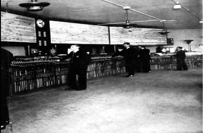
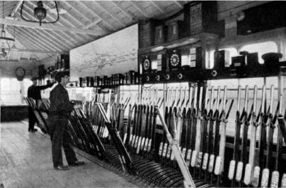
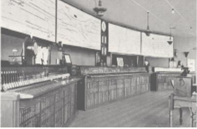
Interior of the Brighton Cabin with 225 levers.
At the time the photographs was taken two additional men were being trained. The normal staff employed on this locking farm is :-
For each of the two day shifts 3 signalmen, and for the night shift 2 signalmen,
The lever interlocking circuits are controlled through contact shafts on the front of the frame, while operation and selection
circuits have their contacts fitted to shafts on the back of the frame. Both sets of contacts are of the high speed air break type,
and can be observed, for maintenance purposes, through glass panels in the sheet steel casing surrounding each section of the
power frame.
The Style M.2 Illuminated Diagrams have been specially designed for this cabin. The background of the diagrams is of pale
green shade to lessen the possibility of eyestrain from constant observation, and the particular colouring of the track circuits
has been chosen as being the most easily followed. Two complete diagrams are provided and, as will be noted from the
illustration, are fixed above the frames and at an angle of approximately half the displacement of the power frame sections.
Relay Room
Brighton
Metal Rectifier Charging Plant for Point-Machine Batteries
The cables from the power frame and diagrams, together with all cables from the track, are led into a cable compartment
below the power frame floor and from there are taken through suitable ducts to the adjacent relay room, a part of which is
shown opposite. The main transformers, with their switches, fuses and power distribution board, are also housed in the relay
room. The cables from outside the cabin are multicore and are terminated in the relay room on porcelain terminal blocks, from
which flame-proof wires connect to the relays.
A.C. relays are used for all purposes. A new type of relay has been used for point indication, viz., the Style Q. three-position
vane relay, with a complement of 8N and 8R contacts, which enables a considerable economy to be obtained by the
elimination of many repeater relays and relay cabinet space. Previous Southern Railway practice has been continued in the
method of wiring, and in placing fuses and indication resistances close to the relays to which they refer.
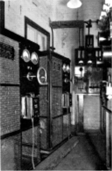
The accumulator battery is housed below the relay room on track level, with the Westinghouse metal rectifier trickle charging
plant and switch gear in an adjacent compartment (see opposite page). In addition to supplying the point machine current, the
battery is tapped at 10-volts to supply the power frame interlocking magnets in an emergency.
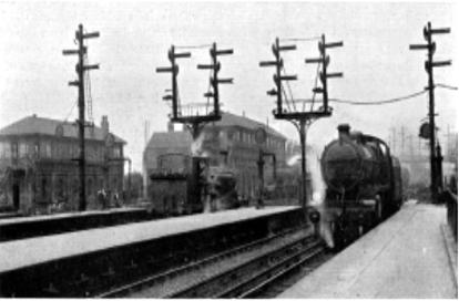
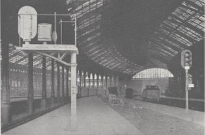
Brighton Station Starting Signals etc. before alterations
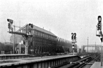
Brighton Station Starting Signals etc. after alterations
The running signals are identical with those between Brighton and Coulsdon, and are supplemented in a number of cases by
optical route indicators. The platform intermediate signals are not worked from levers, but repeat the starting signals. The
route indicator associated with each platform intermediate signal shows the letter " M " or " S " according to whether the
main signal or shunt signal on the starting signal post is showing a " proceed " aspect.
A number of different signal arrangements are illustrated. The two pictures above, taken from a similar viewpoint, afford a
clear comparison between the old mechanical and new colour light signalling.
Brighton Platforms 5 & 6
Brighton Platforms 1 & 2
The running signals are identical with those between Brighton
and Coulsdon, and are supplemented in a number of cases by
optical route indicators. The platform intermediate signals are
not worked from levers, but repeat the starting signals. The
route indicator associated with each platform intermediate
signal shows the letter " M " or " S " according to whether the
main signal or shunt signal on the starting signal post is
showing a " proceed " aspect.
A number of different signal arrangements are illustrated. The
two pictures, taken from a similar viewpoint, afford a clear
comparison between the old mechanical and new colour light
signalling.
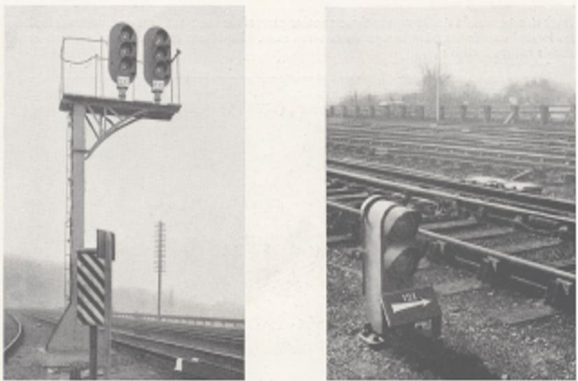
Automatic Signal
Shunt Signal
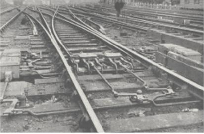
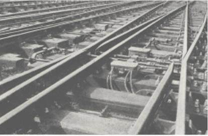
Style M.3 D.C. point machines are employed on all power operated points. The single switch and slip layouts are of the usual
design and do not require any special mention. The illustrations below show two power point layouts which are of
considerable interest. The upper photograph shows a " three-throw " layout operated from two separate machines ; while the
lower one is of a movable diamond layout of which there are two sets in the yard, and which are unusual in that the diamond
includes a slip connection.
Track circuits are of a similar type to those on other parts of the line; and here also, the track feed sets are located outside the
cabin in separate cast-iron cases. Impedance bonds are used when there are double rail track circuits.
Three-throw Point Layout operated by two Style Point Machines
Movable Diamond Layout
A diagram of the various cabins abolished is shown alongside.
From this it will be noted that altogether 24 cabins involving
1,093 levers, have been totally abolished, while 9 cabins
having 324 levers are normally switched out. This leaves only
8 cabins in regular service to handle the exceptionally heavy
traffic, not only to Brighton, but to Worthing, Eastbourne,
Portsmouth and several other branch lines.
The whole of the work (with the exception of the power frame
at Brighton, which was erected by this Company) was installed
by the Southern Railway and reflects the very greatest credit
upon the organization and skill of the Signalling Staff, and
which was further demonstrated during the various openings.
The work was completed in four stages and the new signalling
brought into service without any interruptions to traffic.
The first section, that between Coulsdon and Balcombe, was
brought into use on Sunday, June 5th, 1932, in six hours ;
the next, Balcombe to Copyhold Junction, on Monday, October
3rd, in fifteen minutes for each line ; then followed the section
Hayward's Heath to Preston Park, inclusive, on Sunday,
October 6th, in one hour ; and finally, Brighton Station on
Sunday, October 16th, in approximatey 61/2hours
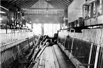
BRIGHTON’S SIGNAL CABINS
Brighton North cabin as first installed in 1871
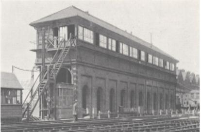
Brighton South Cabin Installed 1881
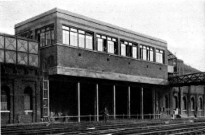
The exterior of Brighton Cabin 1933
As a concluding note to this description of the latest signalling
installation at Brighton some brief reference to the earlier
installations may be of interest, as they constitute an
outstanding and unique record of the manufacture of Railway
Signalling Appliances.
The first installation was put into service about the year 1871,
the materials being supplied and installed by Messrs. Saxby &
Farmer. A general view of the layout is shown in the picture
above. Ten years later the station was considerably extended
and remodelled, and again Messrs. Saxby & Farmer were
entrusted with the supply and installation of the necessary
apparatus. The illustration below is a diagram of the layout of
tracks and signalling at that time, while views of the largest of
the three cabins are shown on the page opposite. For the
purpose of comparison a view of the interior of the new cabin
is also shown opposite.
Thus in a period extending over 60 years, during which three
installations have been provided, the same firm, under the title
first of Saxby & Farmer, and subsequently The Westinghouse
Brake and Saxby Signal Company, Ltd., have supplied the
necessary materials.
Interior of the new Cabin showing 225-Lever Point Frame
with all electric interlocking

240 Lever Mechanical Frame in Brighton South Cabin. Note Mechanical Locking
THE BRIGHTON BRANCH OF A.S.L.E.&F. WEBSITE.
HAS NOW BEEN MOVED TO A NEW SITE CALLED
IGNITING THE FLAMING OF UNITY
https://ignitingtheflameofunity.yolasite.com/
PLEASE CLICK ON THE IMAGE BELOW
TO TRANSFER TO THIS NEW SITE
CLICK ON THE ABOVE IMAGE TO TAKE YOU
TO THE NEW UPDATED COMBINED AND WEBSITE
IGNITING THE FLAME OF UNITY WEBSITE
https://ignitingtheflameofunity.yolasite.com/
THIS WEBSITE COMBINES THE FOLLOWING WEBSITES
THE BRIGHTON A.S.L.E.&F., THE BRIGHTON MOTIVE POWER DEPOTS
& THE SUSSEX MOTIVE POWER WEBSITES
WHICH EXPLAINS THE EVOLUTION OF THE FOOTPLATE GRADES AND THE
HISTORY OF THEIR TRADE UNIONS AND THE STRUGGLES TO IMPROVE
THEIR WORKING LIVES