IGNITING THE FLAME OF UNITY
THE HISTORY OF THE
BRIGHTON BRANCH OF A.S.L.E.F.
|
|
|
BARNHAM STATION
1st AUGUST 1962
INVOLVING BRIGHTON MOTORMAN ALFRED (NORMAN) LIGHT
By Colonel W.P. Reed
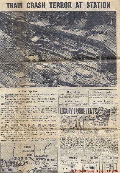
The inquiry into the derailment of a passenger train at about 11.3 a.m. on the 1st August at Barnham in the Southern
Region, British Railways.
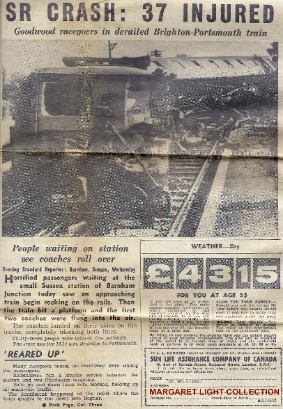
The 10.17 a.m. Down electric passenger train from Brighton to Portsmouth Harbour, travelling at moderate speed under
clear signals, became derailed at partially open facing points on the approach to the station and was deflected on to the
platform ramp. The first and second coaches overturned before the train stopped, but fortunately no one was seriously
injured though 37 of the 250 passengers and the driver of the train required treatment in hospital.
The points, which are motor-worked, had been opened by the motor being wrongly energised; a loose washer had bridged
the electrical circuit to enable this to happen.
Rescue and relief calls were made immediately and the response was excellent. In addition to the normal services. Civil
Defence and W.V.S. personnel took part in rescue and relief work. All the injured passengers had left for hospital by
11.55 am. Traction current was removed from the Up and Down lines by the derailment and was kept off thereafter by
Electrical Control until 12.41 p.m. when it was partially restored to enable trains to move between Bognor Regis and
Portsmouth via the loop line at Barnham. There was considerable traffic dislocation as both lines were blocked at the
Brighton end of the station, but special trains and bus services were quickly introduced. The lines were restored to traffic
in the early hours of the next day.
The day was fine and sunny.
IAN NOLAN COLLECTION
DESCRIPTION
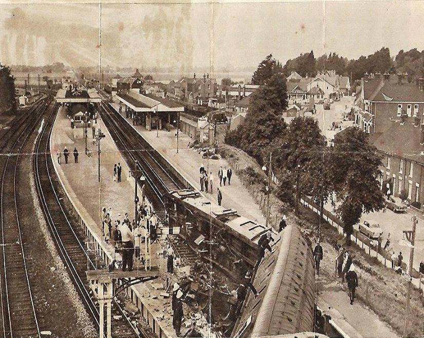
The site
In the Down direction the double track route from Brighton to Portsmouth runs westwards through Ford where it is
joined by the route from London (Victoria) and, 3f miles further on, through Barnham which is the junction for the short
branch line to Bognor Regis to the South. Yapton signal box is about half way between Ford and Barnham. The
alignment through Barnham is straight and the gradient is falling in the Down direction at 1 in 230 on a high bank
towards the station, easing to level through it. The Up and Down main lines run between their respective platforms.
The double line connection to the branch is at the Portsmouth end of the station close to the signalbox, and is facing for
Down trains. There is also a loop line connection to the branch from the Down line at the Brighton end of the station
which passes along the back of the Down platform making it an island. The facing points for this connection, which were
partially open to cause the accident, are linked with trailing trap points on the loop leading to a sand drag. The distance
from the toe of the facing switch to the ramp of the island platform is about 45 yards. On the Brighton side of the points
there is a trailing crossover between the Down and Up lines to enable the loop to he used for departures in the Up
direction.
Because they are at a distance from the signalbox, these four turnouts are electric-motor worked, the remainder of the
points and the signals being worked mechanically. No. 7 lever of the 75 lever frame in the signalbox works the trailing
crossover between the main lines, and No. 8 lever the points from the Down main to the loop line and the trailing trap
points on that line. The Down main home signal, which is on a bracketed post with the Down loop home is worked by
No. 31 lever. These two semaphore signals are 516 yards from the facing points which are 305 yards from the signalbox.
The Down starting signals from the Down main and loop lines to the main and branch routes are opposite the signalbox.
There are a number of other signals, and connections at the Portsmouth end of the station, which are not relevant to the
circumstances of this accident.
Each of the four motor-worked points is moved by a separate points machine, though they work in pairs, supplied with
power at 120 volts d.c. from a rectifier which is fed from the 440v. a.c. signalling supply. Nos. 7 and 8 levers controlling
the two pairs of machines, are mechanically connected to circuit controllers which are rotated by the movement of the
levers to make or break circuits as required for reverse and normal operation for each pair of points machines. Each
machine of a pair has separate positive wires with separate contactors in the lever controller for reverse and for normal
movement but the machines have a common return wire.
The arrangement of the circuits at each points machine is such that when the lever is restored to normal in the frame and
the motor responds, the movement of the facing point lock to unlock the points closes the reverse operating circuit. After
the points have moved, the ha1 movement of the facing point lock, to lock the points, opens the normal operating circuit.
When the reverse operating circuit is energised (on reversing the lever) the movement of the facing point lock to unlock
the points closes the normal operating circuit, and so on. The circuits for the normal and reverse operation of the points
machines for No. 8 facing and trap points include contacts through the levers of the signals which lead over them.
There is the usual mechanical interlocking between the levers, electrical detection between the motor-worked points and
the signal levers, and track circuit locking. The mechanical interlocking ensures that the appropriate levers have been
pulled or are normal in the frame to set up a route before the relevant signal lever can be pulled, and the electrical
detection between the motor-worked points and the signal levers proves that at the time of pulling a signal lever the
electrically operated points on the route are in the correct position. The track circuit locking holds the lever if the route
ahead is not clear.
The railway is electrified on the Southern Region third rail 650 volt d.c. system and there is a sub-station which feeds
power to the system situated in the 'V' between the main and branch routes about 45 yards on the Portsmouth side of the
Barnham signalbox. The sub-stations on either side are at Ford, 3½ miles away as already mentioned and at Drayton 3 ¼
miles towards Portsmouth. The sub-station at Bognor is 2 ½ miles away. There is a track paralleling hut at Yapton.
The train
The electric passenger train consisted of three 2-coach sets,
each set comprising a motor coach and trailer coach with a
driving compartment. Screw couplings were in use between
sets and the two coaches of each set were close coupled.
The length over buffers was 129 yards and the weight was
223 tons. The train was equipped with the Westinghouse
automatic compressed air brake with a power equivalent to
73% of the total weight. The coach bodies were of wooden
frame construction steel panelled, with wooden roofs, and
wood and composition floors. They were of compartment
type with corridors but without gangways between coaches.
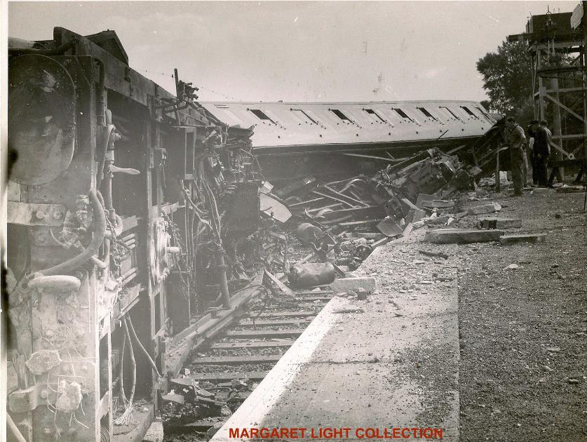
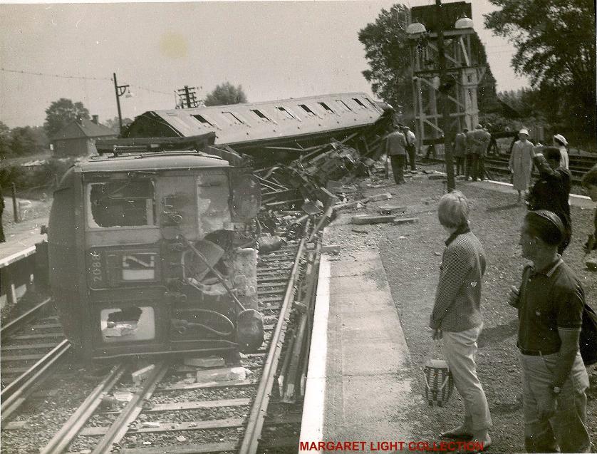
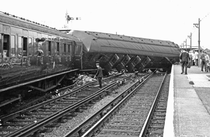
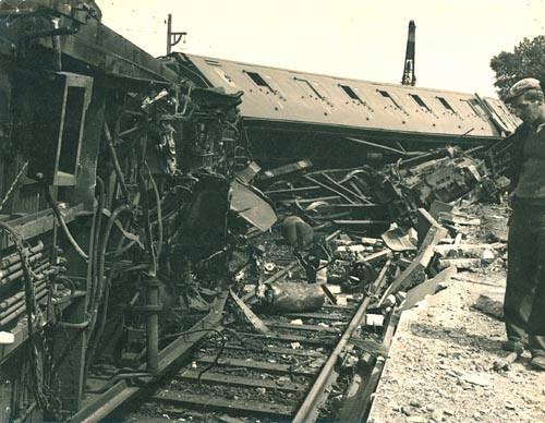
The damage
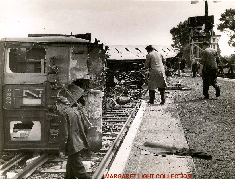
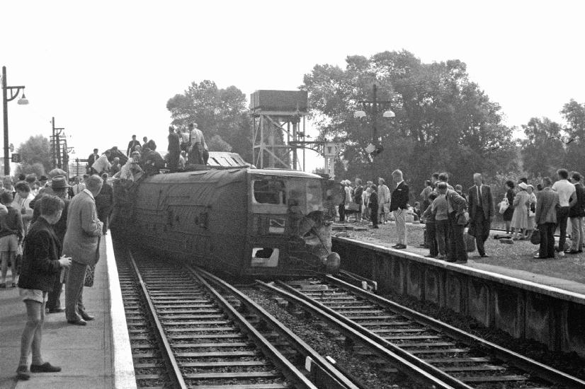
The first coach, a motor one, overturned to the right as the left-hand wheels of the front bogie travelled up the Down platform ramp, and the rear of the coach swung to the right against the Up platform so that the coach came to rest on its side diagonally across both lines between the platforms. It had then travelled 85 yards from the toe of the open switch and 40 yards from the beginning of the platform ramp. The front of the second coach followed the rear of the leading one across to the Up line and it, too, was partly overturned to the right being supported by the platform. These coaches were extensively damaged both in the underframe and the bogies and in the body; all bogies were separated from the underframes. The right side of the body of the first coach and the roof were scored and distorted by contact with the rails and the Up platform coping, and the compartment partitions were separated from the Boor. They did not collapse, however, and most of the seat frames remained firm. The driving cab of the coach was pierced by two of the Down platform concrete coping slabs, one of which then fell across the cab as the coach overturned. Fortunately, the driver held momentarily to his position on the left of the cab and fell on top of the slab and was not injured by it. The interior of the second coach also retained its shape well so that passengers were not crushed. The rear four coaches were not derailed and damage to them was slight.
The accident caused moderate damage to the track and conductor rail over a short length, and the Down island platform ramp was demolished. The coping stones and faces of both platforms required some repair. The signalling and point operating equipment was unharmed.
REPORT
Evidence
Approximately one minute before the accident occurred the rectifier in the sub-station at Barnham went out of service and the circuit breakers between it and the d.c. traction bus bars opened. The traction power supply was then provided from the adjacent sub-stations at Bognor, Ford and Drayton as recorded in the Electrical Control log. The log also showed that the circuit breakers between the bus bars and the conductor rails at Barnham and at Yapton track
paralleling hut opened for the Up and Down lines at 11.2 am. This was caused by the accident. The circuit breakers are remotely
controlled, but they were not restored as the Electrical Controller considered that the circumstances called for investigation; two
minutes later, after he had received the report of the accident from the signalman, the circuit breakers between Barnham and
Drayton and between Barnham and Bognor Regis were opened by remote control to remove electrical pressure on all lines at
Barnham. Subsequent energisations of line were made in accordance with the requirements of the Operating Department.
Signalman F. M. Slater was on duty in Barnham box. He said that the equipment was working normally and that he had
no difficulty on the last occasion before the accident when he reversed No. 8 points to despatch the 10.36 a.m. Bognor
Regis to Victoria train from the loop line platform via No. 8 points and No. 7 crossover reversed. After this train departed
and cleared the crossover at about 10.46 a.m. he re-set the Down main route into the station for the 9.18 a.m. train from
Victoria which arrived at 10.59 a.m. It was followed by the 10.17 a.m. Brighton to Portsmouth train for which he
received "Train Entering Section" from Yapton at 11.0 a.m.; he was not able, however, to lower the Home signal No.
31until the previous train had been divided and the two portions had departed for Bognor Regis and Portsmouth
respectively. When the Down line was clear into the station he had no difficulty in operating No. 31 signal for the
Brighton to Portsmouth train; he did not then take note of the point indicator above No. 8 lever as these points had not
been moved since the previous train had passed. He became aware of the derailment by seeing the smoke and dust arise
from the train and hearing the opening of the breakers in the sub-station and also a noise under the signalbox. He
recorded the time of the accident as 11.3 a.m.
Slater sent "Obstruction Danger" to Yapton but not in the other two directions from which trains were approaching; these
were stopped at the respective Home signals. He agreed that he should have sent a message in these directions also, but
said that it slipped his mind as he became very busy in reporting to Electrical Control and Traffic Control at Redhill.
Slater said that he had not had a power worked points failure since the points had been renewed in May, though one of
the other signalmen had experienced a failure of No. 8 pints a few days previously. This, it was explained, was due to a
weak electrical contact at the controller in the circuit for restoring the points to normal when the lever had been restored
in the frame; the points had not moved to the normal position until the contacts had been adjusted.
Driver A. Light of the 10.17 am. Brighton to Portsmouth train thought that he had been kept waiting for about two
minutes at the Home signal. He said that he accelerated in normal fashion when the signal was cleared and his power
controller was still in series when he came to No. 8 facing points which he saw to be improperly set. He did not notice
the right hand switch rail but saw that the left hand one was away from the stock rail. The switch blade did not appear to
be moving so far as he would see. He said that he closed the power controller and immediately made an emergency brake
application but it did not have time to take effect as his train ran through the open points and was deflected towards the
ramp of the island platform. There was no speedometer in his cab but he estimated his speed at about 20 m.p.h. and he
added that he was about to close the controller and apply the brake for a normal stop in the station when he saw the
wrong lie of the points. After his vehicle had run up the platform ramp and had overturned across the Down and Up lines
he was able to climb out of the broken front window and was helped by the driver of the train ahead, who had been
relieved at Barnham and had come to the scene, to the staff room.
Guard J. E. Sands suffered from shock after the accident and it was some days before he was able to give evidence. He
said that a satisfactory brake test had been made before leaving Brighton and that he saw the Home signals at danger
through the periscope from his position in the rear of the train, and then saw the one for the Main line cleared. After the
train had started to move, he attended to mail for unloading at Barnham until he was thrown to the floor by violent
humping as the train stopped suddenly. He alighted on the off side, saw that the Home signal had been put back to
danger, and went forward to reassure the passengers and to stop them from getting down as he did not then know
that traction pressure had been removed. He did not recollect any heavy application of brakes before the violent bump.
He confirmed that the speed was normal, about 15-20 miles per hour for the run into the station after the halt at the Home
signal.
The evidence of Station Master D. R. Monk, and of Station Foreman F. Broadbridge who was on duty on the Down
platform at the time and who made the immediate arrangements for safety and rescue, confirmed that adequate steps were
taken to protect the Line and to ensure that electrical pressure had been removed, to rescue and succour passengers, and
to organise emergency working. Foreman Broadbridge paid particular tribute to workers from Messrs. Penfolds factory,
which is close to the scene, who came at once to assist in the rescue of passengers. Mr. Monk described the arrangements
made for detraining passengers from the two trains from Bognor Regis and from Portsmouth at the Home signals. He had
hoped at first that it would be possible to bring the trains into the loop line, but decided that the delay would be too long
and arranged for the passengers to be conducted on foot to Barnham; this he said was completed by 11.50 am.
Signal and Telecommunications Sub-Inspector H. R. Green was on the Up platform at Barnham at the time of the
accident, on his way to Horsham. He saw the accident and went at once to the facing points which he saw to be gaping
under the train; as he looked at them the points motor began to run against the clutch. The switch blade did not move as it
was against the wheel flange of the fifth coach. but he thought that the motor was trying to restore the points to normal.
Before he had looked at the points he had seen that the signal was still off, but after the motor began to run he saw that
the signal had been put hack to Danger. He then inspected the coupled trap points on the loop which he saw were normal.
Green went to the signalbox, noted that all levers were normal in the frame, and then reported the accident to his
Inspector by telephone.
Signal and Telecommunications Inspector F. Castle arrived at the site at about 1.30 pm. And carried out a detailed test of
circuits assisted by Sub-Inspector Green. He found all the circuits in order until he applied the volt meter across the
reverse operating wire for No. 8 facing points and the return wire. This test was made on the wiring inside the signalbox
with the line fuses withdrawn. He said that he held the meter across these wires for quite a time and noticed that there
was a varying voltage of between 5 and 15 volts which coincided with the starting of trains from the loop platform line.
There should have been no voltage across the wires and he therefore had a careful examination made which included the
dismantling of the circuit controller. It was then that a washer was found supported on the wiring under the controller
where it was bridging the reverse wire contact to a holding down screw on the frame of the controller, which is joined to
the lever frame and so via the rodding to the rails. When this washer was removed no voltage was recorded between the
reverse operating wire and the return wire.
I asked Mr. J. F. H. Tyler, Chief Signal and Telecommunications Engineer, Southern Region. to describe the effects of
this wrong connection and to tell me of voltage tests which he had subsequently made to ascertain whether this had been
the cause of he points being made to move. He had prepared sketches of the circuit controller showing where the loose
washer was found, and simplified diagrams of the electrical circuits to the points machine. These are attached as
drawings Nos. 1 and 2. Mr. Tyler said that the effect of the connection between the terminal of the reverse operating wire
and the holding down screw underneath was to connect the wire to the running rail via the locking frame and the rodding.
When the points machine was in the normal position, in which the reverse operating wire is connected to the motor and
the other side of the motor is connected to earth via the return wire to the rectifier which is itself earthed by an earth plate,
an electrical circuit was completed from the running rail via the washer and the reverse operating connections of the
points machine, and so to earth. As the running rails are not deliberately earthed an appreciable voltage potential between
them and earth develops when an electric train is accelerating and taking heavy current; this voltage is at its highest at the
mid point between sub-stations. In the Barnham area such voltages are normally very low, but when the sub-station is out
of service they can be considerable. He added that measurements, taken after the accident with the sub-station out of
service, showed electrical pressures of 60 volts between rail and earth when trains were taking heavy current whilst
starting from the station. Such a voltage would have been sufficient to run the motor of the points machine and this
condition was undoubtedly the cause of the points moving on this occasion.
Mr. Tyler said that the circuit controller of No. 8 lever had been overhauled on the 1st April of this year in the normal 5
year programme. The controller was then disconnected mechanically from the frame and examined, and worn parts
would have been replaced. The wiring was not disconnected at overhauls unless it was necessary to replace individual
contact springs, and records were not kept of when this was done. It was not possible to ascertain whether the washer had
fallen into the position where it was found at the last overhaul or whether it had remained concealed in the controller for
many years without causing harm. He was fully satisfied that the maintenance staff would have searched until they had
found it when it first fell, if they had suspected that it had fallen on to the wires under the controller.
Electric traction return current arrangements
Since the current to operate the points machine came from the electrical pressure between the running rails and earth, I
asked Mr. S. Spooner, Maintenance Engineer (Power Supply) Chief Mechanical and Electrical Engineer's Department,
why the running rail was not earthed in the vicinity of signalboxes. He explained that it was not done primarily because it
would cause heavy earth currents to flow which would he likely to give rise to serious damage to buried metallic pipes,
cables, etc., by electrolysis or even by heat and arcing. Even if it were to be a practicable proposition to earth the running
rails the varying effectiveness of the earthing points would mean that potentials would still be likely to occur. It was far a
more satisfactory to confine as much as possible of the return current to the running rails. The poor insulation between
running rails and earth meant that the potential between the positive side of the power circuit and either the negative
return or earth was approximately the same.
IAN NOLAN COLLECTION
Assessment of speed and braking
I asked for details of the speed which might have been reached before the driver applied the brake, and for the stopping
distance of this type of rolling stock in these circumstances. I was advised that if the driver had not moved the power
controller beyond the series position, as he claimed, the train would have reached a speed of about 23 m.p.h. at the facing
points from a start at the home signal 516 yards away, though it could have achieved a speed of 38 m.p.h. in that distance.
if maximum acceleration had been applied by moving the power controller into full parallel as soon as possible. From the
lower speed the train could have stopped in 60 yards with a full emergency brake application, whereas in fact it travelled
85 yards beyond the facing points with two coaches overturned for a short part of that distance. The difference between
these figures is not very great and could well have been due to the driver's reaction time. He might also have applied the
brake simply by taking his hand off the dead man's handle as the train approached the points. This would have caused a
heavy brake application, but only after a delay of five seconds which is incorporated into the braking circuit to enable the
driver momentarily to leave the driving position.
CONCLUSIONS AND REMARKS
I have no doubt that the accident was due to the bridging by the washer of the gap from the reverse operating wire contact
in the controller to the frame of the controller. With the points normal the reverse operating circuit was closed at the
points machine, though open at the points lever controller in the signalbox: there the washer provided a connection from
the reverse operating circuit to the frame of the controller and thence through the locking frame and rodding to the
running rail. As the train started up and took current from the conductor rail there was sufficient electrical pressure
between the running rail and earth to energise the points motor and to open the points. The normal operating circuit was
thereby closed at the points machine. When No. 21 signal lever was restored to normal in the frame the normal operating
circuit was completed and the motor was energised to work the points to normal, which the sub-Inspector heard.
The presence of the washer in the controller was due to a mistake by one of the Signal and Telecommunications
Department staff but I cannot say when it occurred. I can understand that a washer might drop unnoticed and therefore
not be searched for, but nevertheless it should not have happened, and appropriate instructions have been issued in the
Department to emphasise the consequences that can arise from the smallest mistake in signal equipment maintenance.
The electrical pressure between rail and earth became sufficient to cause the points motor to work, after the false
connection had been made, only because Barnham sub-station went out of service. The traction power supply system
envisages sub-stations being out of service from time to time, and signal equipment is protected against the Local effects
of such an occurrence. The circuit to the motor was fully insulated and it would normally have been unaffected by
extraneous electrical pressures; nevertheless, in this case a breakdown in insulation at a critical point made it vulnerable.
It is the aim in railway signalling practice to ensure so far as may be possible that any one fault does not result in a
dangerous condition being set up. The chances of this kind of fault occurring again are remote and Mr. Tyler advised me
that so far as he knew there had been no previous instance of a similar occurrence on the Southern Region. There had,
however, been faulty operation of motor worked pints else were on British Railways in the past through false feeds,
though for different reasons; in consequence the advisability had been recognised of providing a contact normally open in
the negative lead from the points motor as well as the operating contacts for reverse and normal in the positive leads,
which would only be closed by the movement of the lever to operate the points. Such an arrangement would have
prevented the faulty operation of the points which happened on this occasion. Mr. Tyler said that there was a programme
on the Southern Region to make this alteration at the 337 motor-worked points which are operated on the same principle
as those at Barnham but that only about one half of the work had been carried out as yet. I am glad to record that a higher
priority for the remainder of the work has been given and that Mr. Tyler hopes that all motor-worked pints will have this
additional protection within the next six months to one year.
 Click on the icon above for the Brighton Motive Power Depots |
 Click on the icon above for the Sussex Motive Power Depots & ASLEF Branches |